Maxwell's equations are a set of partial differential equations that, together with the Lorentz force law, form the foundation of classical electrodynamics and electric circuits.
Maxwell's equations describe how electric and magnetic fields are generated and altered by each other and by charges and currents.
They are named after the Scottish physicist and mathematician James Clerk Maxwell who published an early form of those equations between 1861 and 1862.
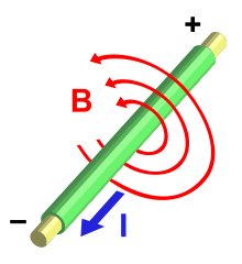
Conceptually, Maxwell's equations describe how electric charges and electric currents act as sources for the electric and magnetic fields and how they affect each other. Of the four equations, two describe how the fields emanate from charges and the other two equations describe how the fields circulate around their respective sources.

Maxwell's equations describe how electric and magnetic fields are generated and altered by each other and by charges and currents.
They are named after the Scottish physicist and mathematician James Clerk Maxwell who published an early form of those equations between 1861 and 1862.
Conceptually, Maxwell's equations describe how electric charges and electric currents act as sources for the electric and magnetic fields and how they affect each other. Of the four equations, two describe how the fields emanate from charges and the other two equations describe how the fields circulate around their respective sources.
The following equations are the conventional formulation of the Maxwell equations in terms of vector calculus using time dependent vector fields. Symbols in bold represent vector quantities, and symbols in italics represent scalar quantities.

-------------------
Ref: Wikipedia

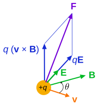
![\mathbf{F} = q[\mathbf{E} + (\mathbf{v} \times \mathbf{B})]](http://upload.wikimedia.org/math/b/5/a/b5a66bbfb93e22f6f60240a135dda69f.png)


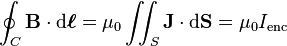

 is the closed
  denotes a 2d surface integral over S enclosed by C